- CBSE Notes Class 12 Physics Electrostatics
Candidates who are pursuing in Class 12 are advised to revise the notes from this post. With the help of Notes, candidates can plan their Strategy for particular weaker section of the subject and study hard. So, go ahead and check the Important Notes for Class 12 Physics Electrostatics
Charge
Charge is that property of an object by virtue of which it apply electrostatic force of interaction on other objects.
Charges are of two types
(i) Positive charge
(ii) Negative charge
Like charges repel and unlike charges attract each other.
Quantization of Charge
Charge on any object can be an integer multiple of a smallest charge (e).
Q= ± ne
where, n = 1, 2, 3,……. and e = 1.6 * 10-19 C.
Conservation of Charge
Charge can neither be created nor be destroyed. but can be transferral from one object to another object.
Recently a new particle has been discovered called ‘Quark’. It contains charge ± e / 3, ± 2e / 3.
[The protons and neutrons are combination of other entities called quarks, which have charges 1 / 3 e. However, isolated quarks have not been observed, so, quantum of charge is still e. ]
Coulomb’s Law of Electrostatics
Electrostatic force of interaction acting between two stationary charges is given by
F = 1 / 4π εo q1q2 / r2
where q1, q2 are magnitude of point charges, r is the distance between them and εo is permittivity of free space.
Here, 1 / 4πεo = (10-7 N – s2 / C2)C2
Substituting value of c = 2.99792458 X 10⁸ m/s,
We get 1 / 4πεo = 8.99 x 10⁹N-m2/C2
In examples and problems we will often use the approximate value,
1 / 4πεo = 9 * 109N-m2/C2
The value of εo is 8.85 * 10-12 C2 / N-mC2.
If there is another medium between the point charges except air or vacuum, then εo is replaced by εoK or εoεr or ε.
where K or εr is called dielectric constant or relative permittivity of the medium.
K = εr = ε / εo
where, ε = permittivity of the medium.
For air or vacuum, K = 1
For water, K = 81
For metals, K = ∞
Coulomb’s Law in Vector Form
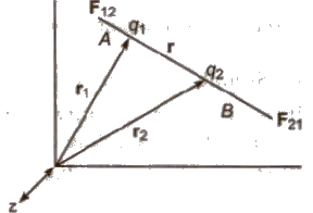
Force on q2 due to q1,
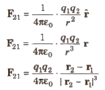
The above equations give the Coulomb’s law in vector form.
Force on q1 due to q2 = – Force on q2 due to q1
F12 = – F21
F12 = q1q2 / 4πε . r1 – r2 / |r1 – r2|3
The forces due to two point charges are parallel to the line joining point charges; such forces are called central forces and electrostatic forces are conservative forces.
Electric Field
The space in the surrounding of any charge in which its influence can be experienced by other charges is called electric field.
Electric Field Lines
“An electric field line is an imaginary line or curve drawn through a region of space so that its tangent at any point is in the direction of the electric field vector at that point. The relative closeness of the lines at some place give an idea about the intensity of electric field at that point.”
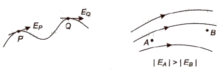
Two lines can never intersect.
Electric field lines always begin on a positive charge and end on a negative charge and do not start or stop in mid space.
Electric Field Intensity (E)
The electrostatic force acting per unit positive charge on a point in electric field is called electric field intensity at that point.

Electric field intensity E =
Its SI unit is NC-1 or Vim and its dimension is [MLT-3 A-1].
It is a vector quantity and its direction is in the direction of electrostatic force acting on positive charge.
Electric field intensity due to a point charge q at a distance r is given by
E = 1 / 4π εo q / r2
Electric Potential (V)
Electric potential at any point is equal to the work done per positive charge in carrying it from infinity to that point in electric field.
Electric potential, V = W / q
Its SI unit is J / C or volt and its dimension is [ML2T-3A-1].
It is a scalar quantity.
Electric potential due to a point charge at a distance r is given by
v = 1 / 4π εo q / r
Potential Gradient
The rate of change of potential with distance in electric field is called potential gradient.
Potential gradient = dV / dr
Its unit is V / m.
Relation between potential gradient and electric field intensity is given by
E = – (dV / dr)
Equipotential Surface
Equipotential surface is an imaginary surface joining the points of same potential in an electric field. So, we can say that the potential difference between any two points on an equipotential surface is zero. The electric lines of force at each point of an equipotential surface are normal to the surface.

(i) Equipotential surface may be planer, solid etc. But equipotential surface can never be point size.
(ii) Electric field is always perpendicular to equipotential surface.
(iii) Equipotential surface due to an isolated point charge is spherical.
(iv) Equipotential surface are planer in an uniform electric field.
(v) Equipotential surface due to a line charge is cylindrical.
Electric Lines of Force
Electric lines of force are the imaginary lines drawn in electric field at Which a positive test charge will move if it is free to do so.
Electric lines of force start from positive charge and terminate on negative charge.
A tangent drawn at any point on electric field represents the direction of electric field at that point.
Two electric lines of force never intersect each other.
Electric lines of force are always perpendicular to an equipotential surface.
Electric Flux (φE)
Electric flux over an area is equal to the total number of electric field lines crossing this area.
Electric flux through a small area element dS is given by
φE = E. dS
where E= electric field intensity and dS = area vector.
Its SI unit is N – m2C-1.
Gauss’s Theorem
The electric flux over any closed surface is 1 / εo times the total charge enclosed by that surface, i.e.,

If a charge q is placed at the centre of a cube, then
total electric flux linked with the whole cube = q / εo
electric flux linked with one face of the cube = q / 6 εo
(i) Electric Field at Any Point on the Axis of a Uniformly Charged Ring A ring-shaped conductor with radius a carries total charge Q uniformly distributed around it. Let us calculate the electric field at a point P that lies on the axis of the ring at distance x from its centre.
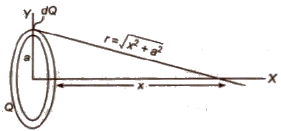
Ex = 1 / 4π εo * xQ / (x2 + a2)3/2
The maximum value of electric field
Ex = 1 / 4π εo (2Q / 3√3R2
(ii) Electric Field due to a Charged Spherical Shell
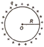
(a) At an extreme point (r > R)
E = 1 / 4π εo q / r2
(b) At the surface of a shell (r = R)
E = 1 / 4π εo q / R2
(c) At an internal point (r < R)
E = 0
(iii) Electric Potential due to a Charged Conducting Spherical Shell
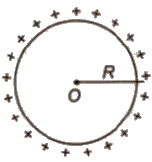
(a) At an extreme point (r > R)
V = 1 / 4π εo q / r
(b) At the surface of a shell (r = R)
V = 1 / 4π εo q / R
(c) At an internal point (r < R)
V = 1 / 4π εo q / R
Therefore potential inside a charged conducting spherical shell equal to the potential at its surface.
(iv) Electric Field and Potential due to a Charged Non-Conducting Sphere
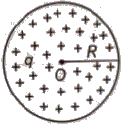
At an extreme point, (r > R)
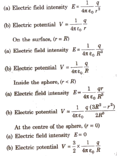
(v) Electric Field Intensity due to an Infinite Line Charge
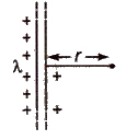
E = 1 / 2 π εo λ / r
where λ is linear charge density and r is distance from the line charge.
(vi) Electric Field Near an Infinite Plane Sheet of Charge
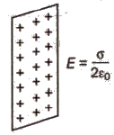
E = σ / 2 εo
where σ = surface charge density.
If infinite plane sheet has uniform thickness, then
E = σ / εo
Electric Dipole
An electric dipole consists of two equal and opposite point charges separated by a very small distance. e.g., a molecule of HCL, a molecule of water etc.

Electric Dipole Moment p = q * 2 l
Its SI unit is ‘coulomb-metre’ and its dimension is [LTA).
It is a vector quantity and its direction is from negative charge towards positive charge.
Electric Field Intensity and Potential due to an Electric Dipole
(i) On Axial Line
Electric field intensity E = 1 / 4 π εo * 2 pr / (r2 – a2)2
If r > > 2a, then E = 1 / 4 π εo * 2 p / r3
Electric potential V = 1 / 4 π εo * p / (r2 – a2)

Ifr > > 2a, then V = 1 / 4 π εo * p / r2
(ii) On Equatorial Line
Electric field intensity E = 1 / 4 π εo * p / (r2 + a2)3 / 2
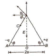
If r > > 2a, then E = 1 / 4 π εo * p / r3
Electric potential V = 0
(iii) At any Point along a Line Making θ Angle with Axis
Electric field intensity E = 1 / 4 π εo * p √1 + 3 cos2 θ / r3
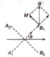
Electric potential V = 1 / 4 π εo * p cos θ / (r2 – a2 cos2 θ)
If r > > 2a, then V = 1 / 4 π εo * p cos θ / r2
Torque
Torque acting on an electric dipole placed in uniform electric field is given by
τ = Ep sin θ or τ = p * E
When θ = 90°, then ‘τmax = Ep
When electric dipole is parallel to electric field, it is in stable equilibrium and when it is anti-parallel to electric field, it is in unstable equilibrium.
Work Done
Work done is rotating an electric dipole in a uniform electric field from angle θ1 to θ2 is given by
W = Ep (cos θ1 – cos θ2)
If initially it is in the direction of electric field, then work done in rotating through an angle θ, W = Ep (1 – cos θ).
Potential Energy
Potential energy of an electric dipole in a uniform electric field is given by U = – pE cos &theta.
Dipole in Non-uniform Electric Field
When an electric dipole is placed in a non-uniform electric field, then a resultant force as well as a torque act on it.
Net force on electric dipole = (qE1 – qE2), along the direction of greater e ecmc field intensity.
Therefore electric dipole undergo rotational as well as linear motion.
Potential Energy of Charge System
Two point charge system, contains charges q1 and q2 separated by a distance r is given by U = 1 / 4 π εo * q1q2 / r
Three point charge system
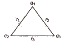
U = 1 / 4 π εo * [q1q2 / r1 + q2q3 / r2 + q3q2 / r3
Important Points
When charge is given to a soap bubble its size gets increased.
In equilibrium for a charged soap bubble, pressure due to surface tension
= electric pressure due to charging
4T / r = σ2 / 2 εo
or 4T / r = 1 / 2 εo (q / 4 πr2)2
or q = 8 πr √2 εo rT
where, r is radius of soap bubble and T is surface tension of soap bubble.
Behaviour of a Conductor in an Electrostatic Field
(i) Electric field at any point inside the conductor is zero.
(ii) Electric field at any point on the surface of charged conductor is directly proportional to the surface density of charge at that point, but electric potential does not depend upon the surface density of charge.
(iii) Electric potential at any point inside the conductor is constant and equal to potential.
Electrostatic Shielding
The process of protecting certain field from external electric field is called, electrostatic shielding.
Electrostatic shielding is achieved by enclosing that region in a closed metallic chamber.
Dielectric
Dielectrics are of two types Non-polar Dielectric The non-polar dielectrics (like N2, O2, benzene, methane) etc. are made up of non-polar atoms/molecules, in which the centre of positive charge coincides with the centre of negative charge of the atom/molecule.
Polar Dielectric
The polar dielectric (like H2O, CO2, NH3 etc) are made up of polar atoms/molecules, in which the centre of positive charge does not coincide with the centre of negative charge of the atom.
Capacitor
A capacitor is a device which is used to store huge charge over it, without changing its dimensions.
When an earthed conductor is placed near a charged conductor, then it decreases its potential and therefore more charge can be stored over it.
A capacitor is a pair of two conductors of any shape, close to each other and have equal and opposite charges.
Capacitance of a conductor C = q / V
Its 81 unit is coulomb/volt or farad.
Its other units are 1 μ F = 10-6 F
1 μμ F = 1 pF = 10-12 F
Its dimensional formula is [M-1L-2T4A2].
Capacitance of an Isolated Spherical Conductor
C = 4 π εo K R

For air K = 1
∴ C = 4 π εo R = R / 9 * 109
Parallel Plate Capacitor
The parallel plate capacitor consists of two metal plates parallel to each other and separated by a distance d.
Capacitance C = KA εo / d
For air capacitor Co = A εo / d
When a dielectric slab is inserted between the plates partially, then its capacitance.
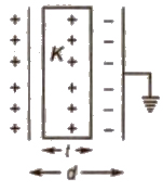
C = A εo / (d – t + t / K)
If a conducting (metal) slab is inserted between the plates, then
C = A εo / (d – t)
When more than one dielectric slabs are placed fully between the plates, then
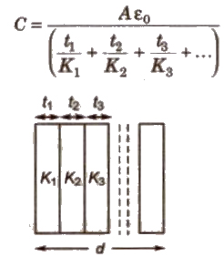
The plates of a parallel plate capacitor attract each other with a force
F = Q2 / 2 A εo
When 9. dielectric slab is placed between the plates of a capacitor than charge induced on its side due to polarization of dielectric is
q’ = q (1 – 1 / k)
Capacitors Combination
(i) In Series
Resultant capacitance = 1 / C = 1 / C1 + 1 / C2 + 1 / C3 + ….
In series charge is same on each capacitor, which is equal to the charge supplied by the source.
If V1, V2, V3,…. are potential differences across the plates of the capacitors then total voltage applied by the
source
source
V = V1 + V2 + V3 + ….
(ii) In Parallel
Resultant capacitance C = C1 + C2 + C3 + ….
In parallel potential differences across the plates of each capacitor is same.
If q1, q2, q3 are charges on the plate of capacitors connected in parallel then total charge given by the source
q = q1 + q2 + q3 + ….
Electric potential energy of a charged conductor or a capacitor is given by,
U = 1 / 2 Vq = 1 / 2 CV2 = 1 / 2 q2 / C
Redistribution of Charge
When two isolated charged conductors are connected to each other then charge is redistributed in the ratio of their capacitances.
Common potential V = q1 + q2 / C1 + C2 = C1V1 + C2V2 / C1 + C2
Energy loss = 1 / 2 C1C2 (V1 – V2)2 / (C1 + C2)
This energy is lost in the form of heat in connecting wires.
When n, small drops, each of capacitance C, charged to potential V with charge q, surface charge density σ and potential energy U coalesce to from a single drop.
Then for new drop
Total charge = nq
Total capacitance = nl/3C
Total potential = n2/3 V
Surface charge density = nl/3 σ
Total potential energy = n2/3 U
Van-de-Graaff Generator
It is a device used to build up very high potential difference of the order of few million volt.
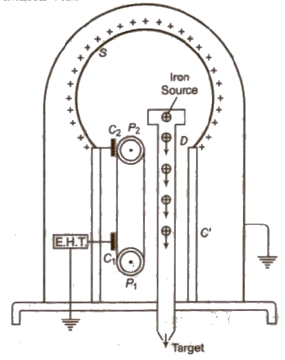
Its working is based on two points
(i) The action of sharp points (corona discharge)
(ii) Total charge given to a spherical shell resides on its outer surface.
(ii) Total charge given to a spherical shell resides on its outer surface.
Lightning Conductor
When a charged cloud passes by a tall building, the charge on cloud passes to the earth through the building. This causes a damage to the building. Thus to protect the tall building lightning, the lightning conductors, (which are pointed metal roe passes over the charge on the clouds to earth, thus protecting building